
28 April 2008: This page is under construction and I shall be editing and adding new material over the next week or so. I will record here significant updates as I make them. I am expecting that it will take some time, if ever, before the new portable 7 foot calibration course is considered ready for general use, so this web page should be regarded as work in progress.
In a post on the course measurement forum thread, Gene Newman, Chairman of the US Road Running Technical Council, asks a rhetorical question to which he does not want an answer:
"As to the electronic unit being 25 times more accurate than a Jones counter, how did this come about (don't answer please)? Why not 30 times or 10 times!"
Despite Gene not wanting an answer, the question is a really good one, and one that provokes deeper thought. I did not want to hijack the original thread which was about whether to choose 450 m or 300 m for a new calibration course, and in any case since I will of necessity have to go into lengthy and somewhat convoluted rationales, these may be unsuitable for the course measurement bulletin board. So I have decided to publish these thoughts as a web page where they can be reviewed by course measurers who have technical expertise and which I will able to refine and update in the light of any comments received and as I carry out experimental work
I am going to start this introduction with what may seem a bit of a digression. But since it was the occasion when a germ of an idea was planted, enjoy it:
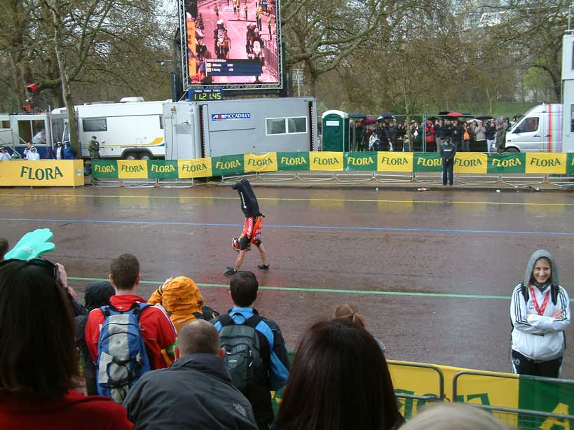
Three weeks ago, my wife and I were really chuffed to get an invitation to join the "bigwigs" for a champagne breakfast in St James to be followed by a place in grandstand no. 1 overlooking the finish of the London Marathon. We had a fantastic day, and I was really impressed by watching the London marathon organisation at work in the finishing straight. What a great job these guys do - and of course there is much much more that we did not see.
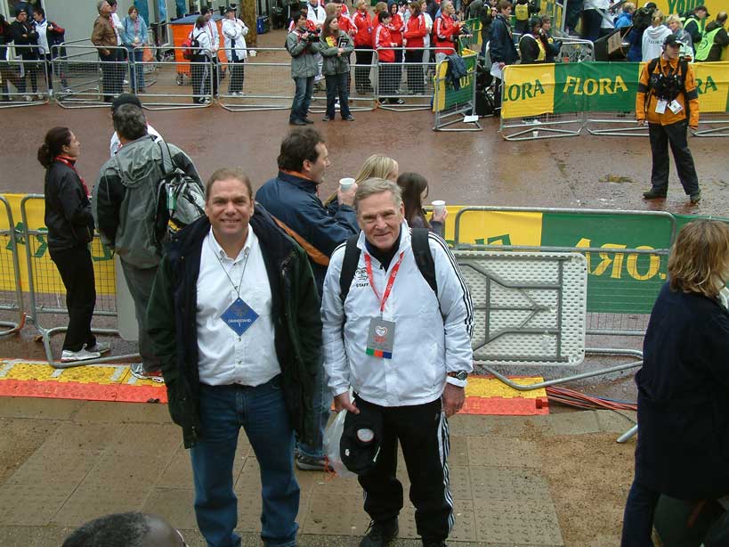
Well, we arrived at the champagne breakfast and looked round for the bigwigs. They were there wearing their gold chains of office (I think there were about 6 London Borough mayors). We found Tom Riegel, who had been helping out his father, Pete, and Hugh Jones with the pre-race validation of the course. After we had finished eating the full English breakfast and quaffed the champagne, I got this snap of Tom with his camera. You can see a bigwig with his gold chain at the nearby table and behind him is my wife with her back to camera ordering us some more champagne at the bar.
During our pleasant breakfast chat which was partly about the undoubted merits of the new Jones Counter (model JR) Tom and I touched on the electronic measurement method and whether it now had much future. Tom has tried electronic revolution counting combined with rim marking. We discussed the neat feature of rim reading which we really liked, namely that it is like putting a ruler down close to the ground and reading the location of the nail against that ruler scale, and to the first approximation the ruler DOES NOT MOVE as you wheel your bike forward, and this makes it easier to determine the reading for the nail location.
Now that little discussion may seem to be no big thing. Anyone can see that the part of the tyre in contact with the road is momentarily stationary as the bike moves forward. It turns out that this so obvious observation is the key to my attempt to build a portable 7 foot long calibration course. However, before I proceed I thought I would share two other pictures from the No. 1 Grandstand. This is located closest to the finish line, which was just to the left of the following picture. You can see we had a good TV monitor showing the progress of the races. There was a race commentary. In this picture you can see one of the leading wheel chair guys, whose trade mark is that he stops about 20 m short of the finish line, gives his chair a push to send it forward over the line, then walks on his hands the last 20 m to the line. Amazing, surely his arm muscles should be clapped out after 26miles? Well, obviously not....
Finally, here is Tom with Pete, who has just arrived from observing the route taken by the leading runners.....
On my bike, one Jones count (on a model JR with 23.6363: 1 gearing) corresponds to 90 mm on the road, so if we read just the nearest full digit the we might be out by half that :45 mm. A measurer with poor reading technique who is confused by the numbers could be out by more perhaps even 90 mm in the the extreme although that is stretching the definition of reading to almost include a mistake!
But 45 mm is not the limit. many measurers when pushed for accurate readings on a calibration course have little difficulty in reading to the nearest half count. That is a maximum error of 22.5 mm.
Some measurers try to read the counter with still higher precision. When its needed I practice is to try judge the position of the digit to the nearest tenth. You need good eyesight or suitable glasses to achieve this, and even then I don't think I can really judge the nearest tenth, but I don't think I am ever more then one and a half tenths off. So if I read and write down say 12345.6, then I think the true value is definitely somewhere between 12345.45 and 12345.75. A maximum error of one and a half tenths corresponds to 13.5 mm.
Is the gearing good enough to avoid degrading that precession? That is something that could be investigated, but I must say that the advance of each digit does appear to me to be very smooth, so that is encouraging. Perhaps an experiment is required unless Tom or Pete can provide an answer based on their gear tooth profile.
In use there is another error which has to be added to the Jones reading error. What is the error in lining up the bike with the nail in the road? This will depend a lot on the measurer's technique. Even with my aging eyes I can still easily resolve the 11 mm head of a PK nail and I routinely line up my two sighting marks to the centre of that nail. Even worse case I am not likely to be out by more than 5 mm.
So for me, when working at maximum precision (trying to judge to one tenth of a Jones count and adding the Jones error to my sighting error) I get 18.5 mm maximum error.
For a measurer reading to the nearest half count and with the same alignment error as me will have a total error of 27.5 mm.
A good measurer reading just whole counts will be accurate around 50 mm, and a novice measurer with poor technique and let us say 25 mm alignment might be have errors high as 115 mm.
In summary I think the maximum error for a Jones counter reading will typically lie between 18.5 mm and 115 mm depending on the technique practised by the measurer. We will work out what this means for a calibration course later.
Potentially this could be very good for counting complete wheel revolutions. If the electronic counter's pick up is near the rim then it certainly has the potential to be accurate in sensing the position with a repeatability of around 1 mm. So excluding the alignment/sighting error discussed above, an electronic counter could in principle count exact complete revolutions with a total error of around 1 mm. This then would be between 13.5 times and 90 times better than a Jones counter. So I think that is the answer to Gene's question. Remember he said, "Why not 10 times or 30 times." He must have realised that it is an over simplification to claim any specific relative accuracy.
Of course there is more to the revolution counter than just the point at which the counter records the complete revolution. This is not how we normally use counters. We need to line up with that little nail at the end of the calibration course. That brings me on to the next section, the use of rim marking and reading which is used in conjunction with revolution counting.
The practice of rim reading is very old. Spoke counting, the simplest form of rim reading, was certainly in use 47 years ago when John Jewell adapted the calibrated bicycle measurement method for use for road races. Of course, after the invention of the Jones Counter in 1972 spoke counting fell into disuse. The revival of rim reading came very recently with interest in using electronic rev counters.
As described by proponents, the interior rim of the wheel is marked between the spokes. In principle these markings could be made as accurately as is needed. One measurer (Mark Neal) with 20 spokes thinks that one can not judge the length of a calibration course between its end nails to one tenth of the spoke interval. ie one can not achieve 11 mm accuracy (taking a 2.2 m wheel circumference). Since separate lineups with the nails at each end of the cal course is required, then I interpret Mark's experience as suggesting that the maximum error at each end is worse than 5.5 mm.
I think that Mark's assessment quite reasonable. When I look at the position of the rim relative to the road on my bike. I note that for my 32mm wheel the rim is about 40 mm above the road. The nail will be also displaced to the side of the rim if the tyre bulges outwards as it does on my bike. It would be easy for me to get more than 5 mm of alignment error at these distances. I assuming I am trying to judge the alignment with my head at the level of the handle bars vertically above the point of interest.
My conclusion is that rev counting with rim reading might be around twice as accurate as the best I can achieve with the Jones Counter i.e. it might achieve an accuracy of 9 mm I would not argue if someone said that he could reliably achieve 5 mm accuracy, but I would ask for his method and to see the analysis which supports the claim of that accuracy.
Using the value of 9 mm then I would answer Gene's question with the statement that rev counting and rim reading is between 2 times and 13 times more accurate than the Jones counter depending on the exact techniques being used in the two cases.
To illustrate the way that these reading errors affect the final calibration constant. I am going first consider the standard minimum calibration course length which is 300 m. The error will occur at both ends so we have to double the figures derived above.
My best Jones counter figure from above will give a maximum error of 2x18.5 mm for the length of the cal course which is 0.012%. This applies to one ride. Averaging over 4 rides will normally reduce this error. It will reduce even more if I clamp the bike wheel when turning at the end of each ride. This will reduce the number of counter reading errors I have to include, but it will not affect the 8 alignment errors which occur at each end of the 4 rides.
For the rev count with rim reading we have only the rim reading error which I have assumed is 9 mm at each end and 18 mm total for one ride the overall precision is 0.006%. This will tend to reduce when 4 rides are averaged, but note there is no gain to be obtained by clamping the bike wheel on turning, since all the errors are effectively alignment errors.
None of these numbers give any concern. Calibration precision on a 300m course will be fine whichever counter is used.
What is needed for my proposed 7 foot calibration course? I am going to set a much more modest target accuracy of 0.03%. The reason for this is that my 7 foot calibration course is not going to be of much use when faced a full normal measurement. I am never going to be able to ride 7 feet with the same wobbles and same speed and therefore wind resistance as I will encounter when riding a measurement ride of a real course. The application I envisage is in checking the variation of calibration constant with difference surfaces. I may encounter a section of gravel or grass. How much will be acceptable without rendering my overall measurement inaccurate?
To achieve 0.03% accuracy on one ride of a 7 foot course (i.e. 2.1 m) I need a maximum error of not more than 0.3 mm at each end. I may be able to relax this a bit if I don't have systematic errors and can average multiple rides, but it is a tall order - more than ten times improvement in precision over the best so far claimed for rim reading. But perhaps not completely out the realms of possibility if one can actually line up the rim measuring scale virtually touching the nail.
There is one thing I don't want to have to do, and that is to mark the whole wheel rim with divisions accurate to much better than 1 mm. So I am going to employ a trick. I will use a solid tyre (which will reduce thermal variations, and eliminate pressure variations.) I will make the calibration course exactly one wheel rotation long - that is how I got 7 foot - it is roughly the 2.136m circumference of my solid tyre. This will mean that I only have to deal with at most 20 mm of variation on different surfaces. My precise scale only needs to be quite short. I will have to sense exactly one complete revolution but here is where that observation that Tom and I made over that breakfast comes in. Since instantaneously there is no relative motion between the rim and the nail when the wheel touches the ground beside the nail, I can relax the the requirements on the precision of establishing one exact wheel rotation, and concentrate mainly on the issue of reducing the alignment errors between the scale and the nail.
So now we get to this ridiculous idea of a 7 foot calibration course. How did it come about? If you look at my posting on 26 April in response to Pete's thread New Proposed Methods you will see that I was thinking that a calibration course of one tape length ie 50m long might be useful I said,
" There could be some use for a modified technique over specially set up 50m calibration courses for the purpose of determining corrections for surface roughness variations between the calibration course and the race course"
What I had in mind was using my solid tyre which is rather insensitive to most of the normal variables which affect pneumatic tyres. For solid tyres the variation of calibration constant on different surfaces is one the larger effects. I also had in mind that if one made the calibration course an exact number of wheel revs long, one would not need to mark the whole rim. Furthermore it would be possible to reverse the usual arrangement and use the tensioned steel tape as the scale and put a single pointer on the wheel which would contact the tensioned steel tape and enable really accurate readings to be made. If 1mm could be achieved at both ends of a 50 m calibration course this would give me an error of 0.004% ample for the purpose I had in mind. The procedure then would be calibrate the solid tyre with normal riding on 300m+ calibration course. But then do a pushing calibration with the front wheel weighted with a static load equal to the force I exert in normal riding, but with the bike pushed along the line given by the stretched steel tape. This latter would be done first on a portion of the surface of my normal 300m + calibration course, and then when I was measuring the real race on variable surfaces including grass and gravel, I could obtain a pushing calibration by stretching out the 50m tape on those surfaces and comparing the result with the home course. This would provide a correction to the normal riding calibration which I had obtained at the home course which would then be applicable for normal riding on that grass or gravel.
So that is a long and convoluted process, which I would not like to do too often, but I thought I might find it worthwhile if I collected some real data on those different surfaces.
Now to test the process I thought why not try it out on my drive with a one wheel revolution course - that is about 7 foot.
I therefore collected some equipment and set up a crude experiment over a 7 foot course as seen below.

The two rulers are raised from the ground, and you can see the piece of yellow cardboard glued onto a spoke. This is going to be trimmed and it will form a pointer on both sides of the wheel to nearly contact the rulers. I decided to try and measure on both sides to increase accuracy and avoid any errors if the front wheel was not pointing straight ahead.
That piece of card needed trimming to pass by the brake blocks. See this being done in the picture below, but not quite complete -I still need to cut a notch for the brake blocks.:

Of course this would need better engineering for proper use, but I figured that I could use the cardboard model as a template for a metal one snipped to shape from a piece of tin can.
The trial worked quite well but revealed some limitations. 12 years ago I had measured this wheel and solid tyre doing 7200 Jones counts on a 650.60 m calibration course. So I can calculate the wheel circumference to be 650.6/7200*23.6363 = 2136 mm. I set the zero of the two rulers at 2000 mm. I rolled the bike along beside the tape and the pointer came down close to the rulers, and was stationary clearly somewhere between 130mm and 136 mm on the rulers. It was still rather difficult to read exactly. The pointers did not quite touch the rulers, and looking from the ideal position above the handle bars my eye sight was not good enough to read the mm. I am saying my reading was about 2133+/- 2 mm. So that is at least in the right ballpark.
The eyesight problem could be solved by taking a photograph from handle bar level. Here is a test picture I took of a tape with my zoom camera at handle bar level. You can clearly see the mm marks. The camera shake shows up because this was done in dim light hand held with a 0.25s exposure.

Please ignore the camera shake. Just look how far apart those mm divisions are. With a fine pointer surely I shall be able to read to around 0.2 mm.
I am present working to achieve that. I have bought a 2.4 m steel bar which chopped down to about 2.136 m will form the transportable base line, eliminating the need for messing around with nails in poor surfaces. I am rethinking a lot of details of the pointer, the scale, and the camera arrangements.
6.30 am Tuesday 29 April. Last night I went to sleep mulling over an arrangement involving the use of MIRRORS to photograph the relative positions of a pointer and scale, one of which would be attached directly to the side of the tyre close to the contact with the ground, and the other fixed to my 2.13 m steel bar.
Over tea this morning I have thrown out the idea of MIRRORS- too messy to engineer. Too many things need lining up and fixing firmly so errors may build up. This morning's idea is HINGES! A pointer mounted on a hinge will be flipped open so that the pointer rests in contact with a mm division scale attached to the flat surface of the rim between the spokes. This will be 40 mm above the ground so the scale wont quite come to an instantaneous rest when the tyre under it touches the ground. However the movement is very small. If I sense the wheel rotation position by a pointer fixed to the front fork and pointing to a mark on the tyre on the opposite end of the diameter of the wheel which passes through the scale, then I should easily be able to fix the rotation at that point accurate to 1 mm. That will be at a radius of about 330mm. The rim scale is just 40 mm from the ground. 1 mm error in rotation at 330mm will correspond to about 0.1mm on the scale mounted on the rim. So if I can read the scale in a photo to 0.2mm then the max error will be 0.1+0.2 mm = 0.3 mm. I am going to have to measure the distance between the pointers on the hinges. Perhaps I will have 0.2mm error at each end. The total error at each end now builds up to 0.5 mm which is higher than my target which was 0.3 mm. However, I am not trying to do an absolute calibration. In my application I am just trying to detect a change of calibration constant when the apparatus is moved from one surface to another. All I will need to ensure is that the hinge and pointer are rigidly attached to the 2.13m long steel bar. The exact length between the pointers will not need to be determined to very high precision.
There is just a chance that my 7 foot calibration course will be good to 0.03% in determining the relative calibration constant on different surfaces! I really thought that a 7 foot calibration course was a ridiculous concept with my limited engineering skills. This is going to be incredibly precise with a longer calibration course such as 51.26 m (24 wheel rotations). It will also be great for measuring pneumatic tyre changes due to temperature and pressure. One just needs the hinges securely fixed to the ground at the two ends of the 51 m cal course and a good line drawn to be followed as one pushes the bike along.
10.17 am Tuesday yet another redesign! It is now a single hinge carrying the pointer glued onto the rim, and when open this reads directly on the tensioned steel tape, or in the case of the 7 foot portable model onto rulers afixed to the steel bar. Camera recording of the pointer reading still seems the best option despite the work of having to subseuently process the images on the computer.. I am now off out to buy a suitably sized hinge....
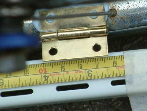
12.21: I got a cheap hinge. I found it wobbled a bit, so I banged the pin with a hammer to bend it a bit and tighten it up. I did a trial mount with blutack. Here it is in the stowed position which passes the break blocks.

Now here are the two readings for my first decent 7 foot calibration "push".

I make this reading on the right hand edge of the hinge 2199.1 mm OK so argue about the 0.1. I read it in photoshop before I threw pixels away for this web image.
This one seems to come out at about 62.6 mm. I am not too happy that the wheel is not nestling up against the steel bar - but that will come with practice, and I need to pin the bar to the ground to stop it getting pushed around!
So for the first measured wheel rotation I get 2136.5 mm. That compares quite well the the 12 year old figure noted above of 2136mm, but then that was loaded with my weight. So far today the bike front wheel is not loaded.
I think I will araldite the hinge in position and let it set this afternoon.
Wed 30 April 0930: The araldite has set. looking at it this morning I am wondering whether a pointer will be useful. I can see how to install one quite neatly, which I am testing with a bit snipped from a coca-cola can and stuck in position on the hinge with blu tack. Here it is in the stowed position:

and deployed:

and here is a slightly blurred view of what a reading will look like. The metal bracket could be made thicker for stability and a tiny pointer mounted at the end for exact reading to reach the target of 0.2 mm:

I think I will do this morning's experiments using the hinge as the pointer with the set up I had yesterday since I had got that tape raised to about the hinge height of 32 mm above the ground.
I had thought that when I come to do the 50m cal course measurements I would be raising the tape on 30 mm thick blocks of wood at the two places where readings were to be made. However, looking at the above I am now thinking that it will be simpler to have the tape on the ground and use the pointer. Reading point is now getting quite some distance transversely from the line along which the wheel is rolling. The tip of the pointer is 29 mm from the line. Small rotations of the handlebars will effect the reading. If say I want to be within 0.1mm, then at the outboard end of handle bars measuring say 2x 300m wide. I must be positioned consistently to 1 mm. I think this is why I need to nestle the tyre up against the correctly aligned straight edge of the 7 foot calibration course. I am not sure about the 50 m calibration course. I want to achieve a higher percentage accuracy on that, but I can afford to lower the precision of the readings to something like 1 mm. That has yet to be assessed.
The other option is a hinged pointer on the ground that flips over a scale along the centre line of the rim. Then movements of the handlebars will have reduced effect. However, I might have to contend with some imprecise measurement of the separation of the hinged pointers using the steel tape. I possibly could get enough accuracy of the 7 foot calibration course. They could be be mounted permanently on the steel bar, and the separation determined once with a lot of care. It just depends what is the sum of the errors for the two configurations and we wont know that until we have an optimised system to evaluate. I will stick with the hinge pointers on the wheel for now despite the obvious safety hazard that if the hinge unlocks from the stowed position during bike riding fast, one could go flying over the handle bars, when the accidentally deployed hinge contacts the brake blocks! Perhaps this type of plastic demountable hinge would be safer?
It is raining steadily so I am going to do some other work. However the thought does occur that I could take the car out of the garage and continue to take measurements with the 7 foot calibration course placed on the concrete floor. I wonder whether I would be allowed to bring the course inside and do a calibration on floor coverings of various types!
It has rained most of the day, but I got out when the sun came out and got some test data confirming the insensitivity of the reading to the exact fraction of the wheel rotation.
I need to add a bit of axplanation here to help explain what is going on as the bike rolls forward. Suppose the bike is moving forward at 10 mph. then the front axle must be moving forwrd at 10 mph. The bit of the tyre touching the ground at any instant is moving forward at 0 mph. If it was not it would be skidding! Now think of the geometry, the bottom of the wheel o mph the axel 10 mph so the top of the wheel is moving forwrd at 20 mph. However in the configuration I am considering I have a pointer indicating on the top of the wheel, but that pinter is attached to the bike so it is moving forwrd at 10 mph. So as seen from the end of that pointer the top of the wheel is moving forward at 20 - 10 = 10 mph. now, if instead of the tyre on the ground I consider the one tenth of the wheel radius up from the ground, that point of the wheel will move forward at 1 mph. Instead of mph now think in movement by steps of 1 mm measured between the top of the wheel and a pointer carried on the bike froint forks. For that movement a point one tenth up the radius from the ground will move 0.1mm. This is what is confirmed experimentally in the following graph -- a bit long winded, but the point has ben queried.
I got 24 images to measure the movement of the pointer as the bicycle advanced in 1 mm steps through 23 mm..

These data confirmed that every movement of the bicyle forward by 1 mm produced an advance of 0.1 mm in the reading on the tape. This is as predicted by the geometry . It is nice to see the discussion between Tom and myself borne out in practice. THE METHOD WORKS.
Then before it rained again I got 2 runs. Later while still very wet I did 3 more runs on the tarmac drive and then moved the calibration course to a concrete edging strip. First movement of a portable calibration course. The results are:
Start mm |
End mm |
1 rotation mm |
||
| Tarmac Drive | ||||
2250.0 |
111.7 |
2138.3 |
dry |
|
2256.7 |
118.7 |
2138.0 |
dry |
|
2264.6 |
126.2 |
2138.4 |
wet |
|
2253.1 |
115.6 |
2137.5 |
wet |
|
2266.2 |
127.9 |
2138.3 |
wet |
|
AVERAGE |
2138.1 |
wet |
||
Concrete
edging |
||||
2255.7 |
116.8 |
2138.9 |
wet |
|
2232.6 |
94.1 |
2138.5 |
wet |
|
AVERAGE |
2138.7 |
I am not at present saying that the difference between 2138.1 mm and 2138.7 mm is the true difference in effective circumference of the wheel on tarmac and concrete . The difference is 0.028% This is about the limit of accuracy I would expect for the method if it was working perfectly, which it is not yet. Therefore I do not think the difference indicates a real difference in the calibration constant between these two surfaces. But may be it is already good enough to be used for a calibration real race measurement, except for the fact that I would have to push the bike instead of riding, and I know that I wobble when riding like every other measurer I have seen riding. (Oh and I have not got the bike weighted with my weight yet)
Improvements to the arrangements are needed, but perhaps it is already good enough to start trying the method on a 50 m tape length..
8 Repeats on tarmac drive but in a different place to yesterday. I am surprised to see 0.07% increase. There is a temperature rise, but not enough to account for it. Is it the different portion of surface or experimental error? Internal repeatablity today has been good on Tarmac.
Followed by 3 places on grass. I had problems with roughness of grass causing hinge pointer to be at wrong height for perfect readings. However there are some wild fluctuations, reason not known. Even so, it seems reasonable to conclude that grass gives about 0.16% increase in diameter - that is odd I was expecting a smaller diameter, but may be that only happens when the tyre is loaded with rider weight.
| Surface | start mm | end mm | 1 wheel rotation mm | ||
| tarmac drive | 2226.7 | 87.0 | 2139.7 | ||
| tarmac drive | 2217.4 | 78.0 | 2139.4 | ||
| tarmac drive | 2236.2 | 96.9 | 2139.3 | ||
| tarmac drive | 2182.0 | 42.5 | 2139.5 | ||
| tarmac drive | 2259.6 | 120.0 | 2139.6 | ||
| tarmac drive | 2266.6 | 126.7 | 2139.9 | ||
| tarmac drive | 2227.0 | 87.6 | 2139.4 | ||
| tarmac drive | 2258.9 | 120.0 | 2138.9 | ||
| average | 2139.46 | standard dev. | 0.30 | ||
| grass position A | 2250.4 | 103.0 | 2147.4 | ||
| grass position A | 2228.7 | 86.5 | 2142.2 | ||
| grass position A | 2252.6 | 105.2 | 2147.4 | ||
| grass positionB | 2253.2 | 111.5 | 2141.7 | ||
| grass positionB | 2250.6 | 108.9 | 2141.7 | ||
| grass position C | 2195.1 | 53.7 | 2141.4 | ||
| grass position C | 2254.9 | 116.0 | 2138.9 | ||
| average | 2142.96 | ||||
| %age change (grass-tarmac) | 0.163 |